Rainwise PVmet series weather stations that can connect to Tigo's Cloud Connect (CC) or Cloud Connect Advanced (CCA) are those equipped with Modbus RTU RS-485. Weather stations sold separately by RainWise. Those models include:
- PVmet-75 Low Cost Entry Level Model
- PVmet-100 Standard Model with Adjustable Irradiance Monitoring
- PVmet-200 Most Popular Commercial Model
- PVmet-200 US Upgraded Anemometer with Ultra Sonic Technology
- PVmet-330 Commercial Model with All Weather Data
- PVmet-150 Thermopile Precision, Adjustable Irradiance Sensor
- PVmet-150/200 Combo Thermopile Precision Irradiance Sensors with Addition of Wind Speed and Direction
(Per manufacturer PVmet sales brochure, RainWise Inc., 2016)
Connecting the Rainwise PVmet Weather Station to the CCA RS-485
The PVmet is supplied with a half duplex RS-485/422 serial port. The default firmware build supports RS-422 only. Custom firmware builds are addressable and support integration into RS-485 networks. Contact RainWise for further information.
Wiring connections are made using the 4-pin screw terminal inside of the PVmet electronics enclosure. The RS-485/422 lines can be terminated with a 120 ohm resistor. This can be enabled by moving the termination jumper, located inside the unit, to the “ON” position. This requires removing the enclosure cover. To do this, remove the 4 screws on the bottom side of the unit.
RS-485/422 Terminals
| A (-) : | Negative RS-485 | |
| B (+) : | Positive RS-485 | |
| Gnd: | Signal Ground | |
| Shield: | Cable Shield and Drain |
RS-485 is rated to 4,000 feet (1,200 m) at 90 kbps. The RS-485 port on the PVmet is surge protected but not isolated.
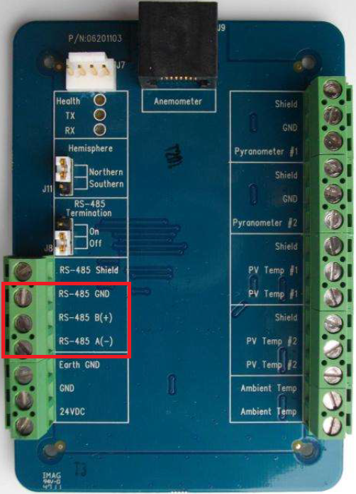
Figure 1:PVmet connection board
Connect a CC or CCA RS-485 port (either RS485-1 or RS485-2) to RS-485 port of the PVmet weather station as described in figure 2.
Note: old versions of CC may refer to the RS-485 port as "optional", nevertheless notation remains the same as in figure 2.
Note: The Tigo CCA has named the + channel of the RS-485 A and the - channel B. The PVmet has named the + channel B and the - channel A. The two + and the two - channels have to be connected. It is mandatory to connect the A from CCA to the B from the PVmet and vice versa.
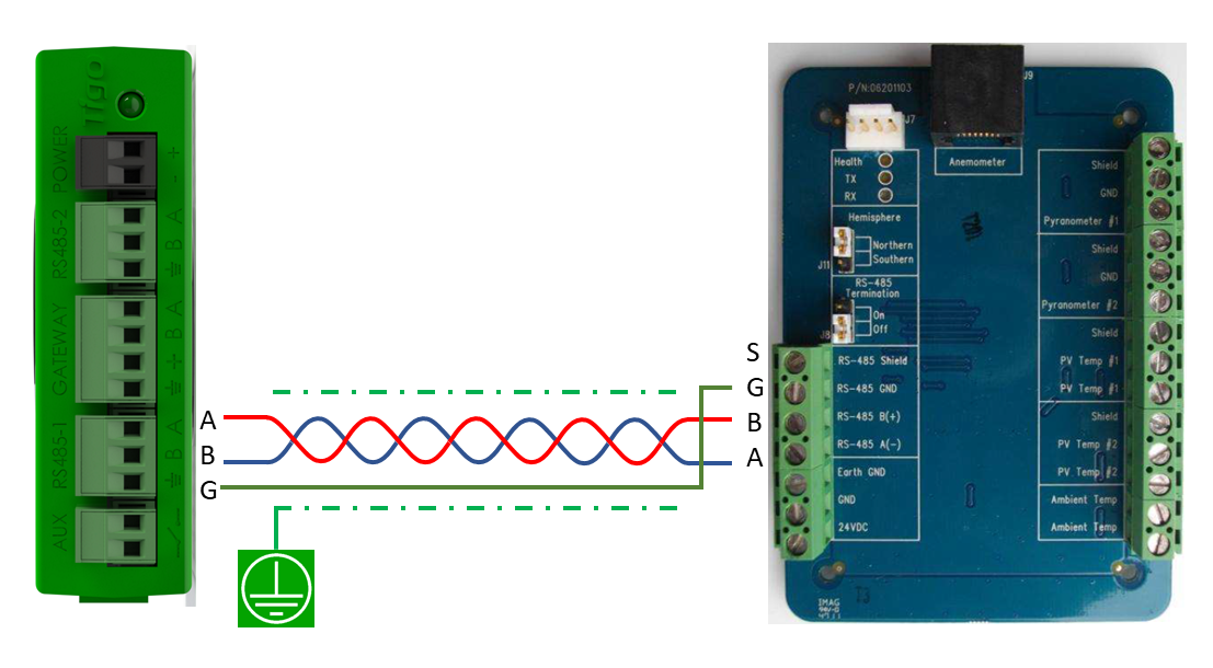
Figure 2: Connection between CC / CCA RS-485 port to PVmet RS-485 port
A to B and B to A
Connect the shield of the RS-485 connection cable only at one end to the ground from the CCA electrical power supply cable that is shown in figure 3.
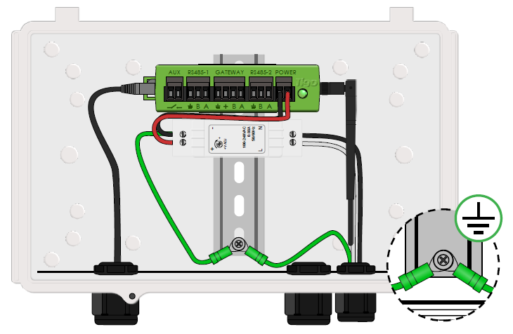
Figure 3: Ground connection Point for electrical Power Supply
Per Rainwise Inc.:
- Use up to 254 PVmet Weather Stations on a single bus using RS485.
SunSpec and Modbus
After setting up the PVmet Weather Station and the RS-485 connection, the PVmet is ready to operate per default settings.
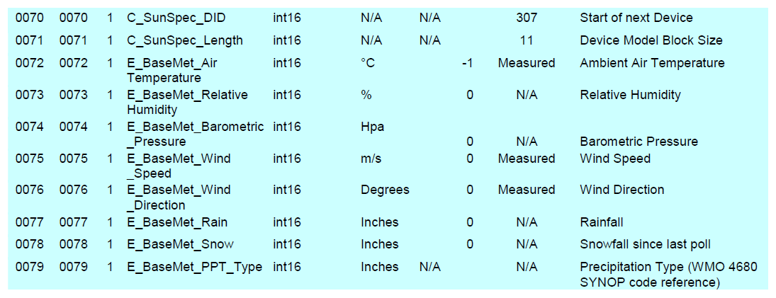
The PVmet series follows the SunSpec standard. Refer to the official SunSpec specifications for application information. The full register map is listed below. The PVMET-200 has the following default communication settings:
Serial/ General
Baud Rate: 9600
Parity: None
Stop Bits: 1
RS-232
Flow control: None
RS-485
Interface Mode: 2-Wire Half Duplex
Modbus
Device ID: 60
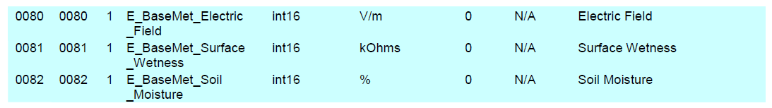
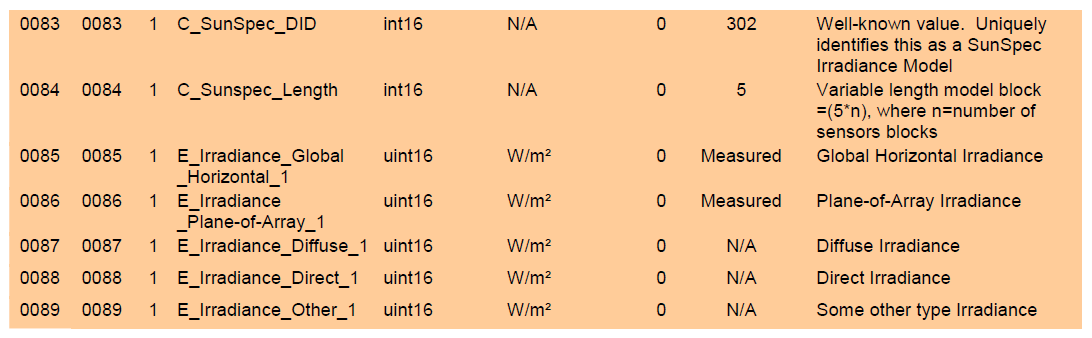
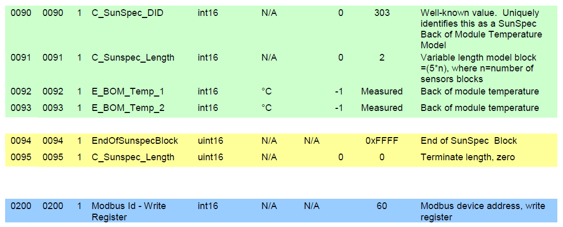
Register Map

Changing Modbus Device Address
If Modbus address is set to 60 and baud rate of 9600 the PVMET does not need programming. The PVMET is set default to SunSpec registry.
For more information click here to visit manufacturer's website and view complete installation and safety manuals.
Monitor at the Tigo Portal
Once device is wired and configured contact Tigo Technical Support via email Support@tigoenergy.com or via phone:
International: 00800.2255.8446
Americas: +1.408.402.0802 ext. 2
Have your meter address ready, and list of parameters you wish to display, and our team will complete the setup so that you can view the meters on your Tigo monitoring portal.