Overview
The Tigo Gateway is a legacy communication device used with older Tigo monitoring systems. Proper Gateway placement is essential for reliable communication with Tigo optimizers and accurate module-level monitoring.
The number of Gateways required depends on:
- Total module count
- Array size and layout
- Physical obstructions
- Distance between array sections
For newer systems using the Tigo Access Point (TAP):
- TAP vs. Gateway
- TAP Placement Requirements
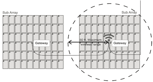
Gateway Capacity and Range
Each Gateway can communicate with up to 120 Tigo optimizers.
For reliable communication, all optimizers should be located within 50 feet (15 m) of the Gateway and have a clear line of sight to the device.
If any portions of the array are more than 50 feet apart, install additional Gateways.
A single Cloud Connect, Cloud Connect Advanced (CCA), or MMU can support up to seven Gateways connected on the same RS-485 communication network.
When Additional Gateways Are Required
Install additional Gateways when:
- The system contains more than 120 monitored modules
- Sections of the array are more than 50 feet (15 m) from the nearest Gateway
- Physical obstructions block communication
- The array is divided across multiple roof planes or separate buildings
Systems with east-facing and west-facing arrays typically require a Gateway on each roof plane.
Gateways in series (Daisy-chained to a single RS-485 cable)
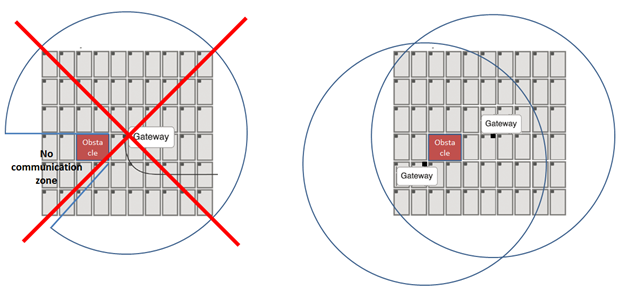
Avoid Obstructions
Communication performance can be reduced by obstacles that block the signal path between the Gateway and the optimizers.
Common obstructions include:
- Chimneys
- Dormers
- HVAC equipment
- Parapet walls
- Significant roof elevation changes
As a general guideline, any height change greater than 3 feet (1 m) should be treated as a potential obstruction.
If communication may be blocked, relocate the Gateway or add an additional Gateway to provide coverage.
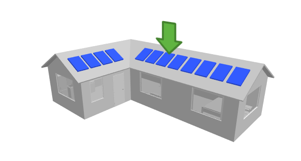
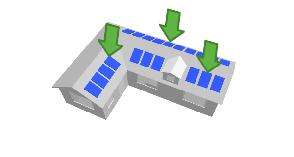
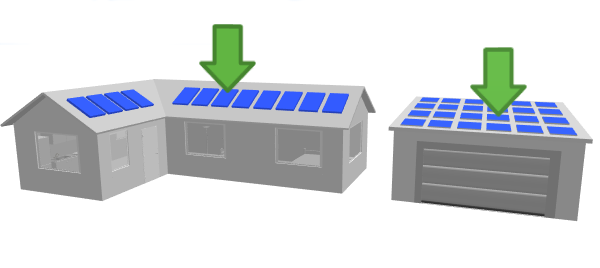
Residential: Example Gateway Placements:
- L-shaped house with one Gateway (location = green arrow)
2. L-shaped house with a dormer, which may need 2 Gateways.
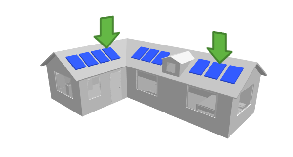
3. L-shaped homes and systems with multiple array orientations may require additional Gateways, as radio signals typically do not penetrate roofing materials effectively.
4. Multiple rooftop arrays separated by significant distance
Installation Requirements
For best results:
- Mount the Gateway directly to a module frame whenever possible
- Position the Gateway close to the center of the area it serves
- Maintain clear communication paths to all monitored modules
- Avoid installing Gateways in attics or locations where roofing materials may weaken the signal
Design Checklist
Before finalizing a Gateway layout, verify:
- All modules are within 50 feet (15 m) of a Gateway
- Physical obstructions have been considered
- Additional Gateways have been added where required
- Separate roof planes have appropriate coverage
- Multiple Gateways are connected using RS-485 communication wiring
Following these guidelines will help ensure reliable monitoring and communication throughout the system.
Legacy Equipment Additional Resources
MMU/Cloud Connect - Gateway Test (legacy)
Maximizer Management Unit (MMU) Overview and Troubleshooting (Legacy)
Network Test - Cloud Connect (CC) Troubleshoot Network Connection
What channel(s) does the TAP or Gateway use to communicate?
Commissioning: Error code troubleshooting on the CC and MMU
Replacing Maximizer Management Unit (MMU) or Cloud Connect (CC) with a CCA